
NPGS, Nanometer Pattern Generation System, allows a user to create a nanometer pattern on a specimen. Generally the beam parameters used are found on the last page of the FIB manual under the "Beam Mode" column "M1", using an aperture size of 100 µm. Zoom is set at 566x. The center-to-center value is set to 3.69 nm.
The calibration of the FIB is dependent on the densities of the specimens. This procedure is specific for the construction of wave guides. The standard line dose is between 80 and 100, producing depths between 500 and 600 nm.
1. Close the initial NPGS Window and re-open the program by clicking on the NPGS Menu shortcut on the desktop. This is done if you are the first user of the software for the day.
![]()

2. Wait 40 seconds for calibration. The FIB only calibrates once per day.

3. Click on DesignCAD files in the upper right pull down bar.

4. Click DesignCAD express and hit any key to continue.
5. Click on the line icon in the upper left.
![]()

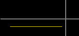
6. Draw a horizontal pattern on the screen. Double click when you have defined the line.

7. Click on the line and press Ctrl+I, a window will open to allow the parameters to be set in the "Vector" window. For point 1, set X:O and Y:O. For point 2, set X:10 and Y:0. You should then set line length to 10. Press Enter, to save the parameters, and close the "Vector" window.

8. To make an array, click on the pull down bar at the top of the screen labeled NPGS > MakeArray.
Cross hairs will appear; click below the left of the line and then above the right of the line using the crosshairs.
9. In the "NPGS: Make Array Function" windows that appears, enter the following data:

9.1. Number of COLUMNs: 1
9.2. COLUMN Spacing (If there are more than one)

9.3. Number of ROWs: 600

9.4. ROW spacing: 0.35 μm (If there are more than 1)
The color of your rows and columns can be changed, but hit (N) twice to proceed. Changing the color of lines and columns defines a different layer to be imaged and this is generally not desired.
NOTE: YOU ALWAYS NEED TO SET THE PATTERN IN THE MIDDLE OF THE SCREEN.

10. Click on the pull down bar at the top of the screen labeled NPGS > MaxMag > 'o' to change/set the origin of the array.

Maximum Magnification Utility

MaxMag: After Moving Origin

11. Click on the pull down bar at the top of the screen labeled NPGS > SetDump.
Click near the array where you want to set the point about three times, or until you see a blue dot appear where your pointer is.
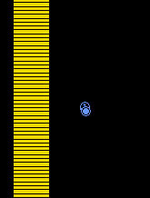

Set Dump Point

12. Click on the pull down bar at the top of the screen labeled NPGS > Save.

Name your file and save it to the current NPGS Project as a type "DesignCADf." At this time, you may choose to close this program if you wish.

13. Right click on the file in the Nanometer Pattern Generation System window. Choose the "Run File Editor" option. Click on "Pattern Name" in the left side of the window.

Parameters will appear on the right side. The user should enter the following parameters for creating a wave guide pattern as shown in the picture:
- Layer 1: Normal Writing
- Origin Offset: 0,0
- Magnification: 566
- Center-to-Center Distance: 3.69 nm
- Line Spacing: 3.69 nm
- Configuration Parameter: 1
- Measured Beam Current (Read off of the FIB): 522.0 pA
- Multiple Pass Mode: Disable
- Line Dose: 100 nC/cm

14. Save the file again in "Run Files" as the same name used before if preferred. Close the "Run File Editor" window.

15. Change "Display File Types" to "Run Files".
16. Select your file and click on DAC(+10,+10) near the bottom left of the window.
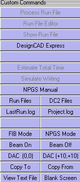
17. Press "NPGS Mode" under Custom Commands.
18. Click on "Process Run File" near the upper left of the screen.

19. Start the FIB and NPGS at the same time. Spacebar will start the NPGS software.
20. Press Esc to manually stop the imaging, or if everything is correct, wait for the timer on the screen to run down. Otherwise, when the program is finished, press Esc twice to get back to the normal screen.
21. Click FIB Mode in the left column to see your pattern on the Hitachi monitor.