1. Focus and register M1-500 off the area of interest. Use M0-50 to return to the saved position.
Click Edit > Select All Pattern Elements, then position a pattern over the pad. Set Area x Zoom to 256 x 4, and click Get Image button.
3. Focus and register M0-50. At Area x Zoom = 256 x 1, manually tilt the specimen to 60 degrees and lock the position.
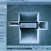
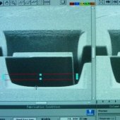
4. Return to the saved spot and use Area x Zoom = 256 x 4 to focus. Register M1-300 for the undercut, then Get Image.
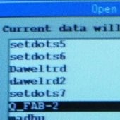
5. From the Edit menu, press Clear to remove the QFAB_2 pattern from the screen.
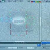
Draw a rectangular box with the following parameters:
- Area x Zoom: 256 x 8
- Dimensions: ~24 x 2
- Time: 10 min.
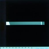
- Scan: see left image.
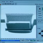
NOTE: Turn the CONTRAST UP and carefully watch both sides of the milling window move towards the center until it is cut through. When complete, press Stop & Close.
8. Select M0-50. At Area x Zoom = 256 x 1, tilt the specimen back to 0 degrees and lock the position.
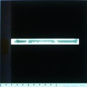
9. At Area x Zoom = 256 x 4, focus register. Check if the back edges are cut. If necessary, perform the mill again by tilting back to 60 degrees, and milling farther up from the bottom edge.
Operating Procedure: Landing the Probe for Lift Out Technique Part 1
