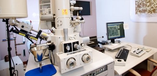
FE-SEM Imaging

Beam Current

FE-SEM Beam Current Stability Graph
FE-SEM beam current stability is shown as a function of emission current over time. The emission current starts near 10 microamps and drops to 5 microamps in 15-30 minutes. It is reset and then drops again at the 45-60 minute mark.

NOTE: You will periodically need to reset the beam current. To do so, click on the Set icon in the Accelerating Voltage window. Check to ensure the beam current is around 10 µA at 15 minutes into your session and again at 45 minutes into your session.

Accelerating voltage set.

Beam current (Ie) becomes more stable over time as contamination is spread evenly over the surface of the emission tip.

Beam Current Stability Animation

Alignment

Alignment Procedure

18 sec. No audio.

Hitachi S-4700 FE-SEM

After selecting Condenser Alignment, the image begins to shift in both the X (horizontal) and Y (vertical) directions. To correct this, it is easiest to eliminate shift first in one direction and then the other. Turn the Y alignment knob until the image shifts only horizontally in the X direction.

See FE-SEM Imaging Operation Step 8 below.

Alignment Demo

55 sec. No audio. Demo host Claire Drom.

Pair of images showing a fuzzier and clearer resolution.
Image before (top) and after (bottom) alignment.

Stigmation

Stigmation Procedure

52 sec. No audio.

Hitachi S-4700 FE-SEM

Find the center point where there is no stretching of the image. This point does not necessarily have to be in focus. Use one alignment knob, either X or Y, to focus the image. Then use the other knob to focus again.

See FE-SEM Imaging Operation Step 8 below.

Stigmation Demo

32 sec. No audio. Demo host Owen Mills.

Two images showing more or less distortion.
Image before (top) and after (bottom) stigmation correction.

Operation

Set icon.

1. If you are the first user of the day, then perform the flashing procedure. See Flashing under Operating Procedures in Hitachi S-4700 FE-SEM. If you do not need to flash, select an operating voltage by clicking in the top right Accelerating Voltage window.


HV control icon.

2. An HV Control dialogue box will appear. Select the desired accelerating voltage. Click ON.


Column setup icon.

3. Click on the Column Set Up icon and select an operation mode. Column icon.


4. Once the operating conditions have been selected, roughly focus the image in high mag mode.

If you wish to change the WD, use the Column Setup menu to select a new WD. Then, adjust the stage in the Z direction until the image is in focus. Check the software and the Z axis knob to make sure the WD is approximately the same on each.


Magnification icon.

5. To find an area of interest, select Low Magnification mode. Do this by clicking on the H/L icon to switch between high and low magnification.


Alignment window icon.

6. If you find that the image shifts locations when you change modes, select a large, distinguishable feature under high mag mode. Then, switch to low mag mode and click the Alignment icon. Select low magnification adjustment and use the Alignment/Stigmation controls to move the feature into the crosshairs. Select Off in the alignment box and close the window. Alignment icon.


7. Move to the area you want to image and focus.


Control board.

8. Once you have focused, click on the Alignment icon. For all alignments, use the Alignment/Stigmation controls on the control panel. Alignment icon.

8.1. Start with Beam Align. A target will appear. Using the knobs, move the beam to the center of the "bulls-eye".

8.2. Next, select Aperture Align. Eliminate any shift in the window using the knobs. It is easiest to adjust so that the image shifts only in one direction (x or y). Use a magnification where you can easily see the shifting and adjust. Then move to a higher magnification (between 50,000-80,000) and repeat. View the alignment demo above.

8.3. Click on Stig Align X and Stig Align Y. Adjust as above, but these often do not need to be changed! View the stigmation demo above.

8.4. Close the window.


Stage lock icon.

9. When the area of interest is identified and the correct working distance and tilt setting are selected, lock the stage. NOTE: DO NOT CHANGE THE WORKING DISTANCE WHILE STAGE LOCK IS ON. You may need to find your location again, then refocus and stigmate. Wait a few seconds until the image stops drifting.


Set icon.

10. Once you are satisfied with the image, check that the beam current is at least 8 µA. If not, click the SET icon to the upper left of the voltage box.


11. Click on the Auto Brightness and Contrast icon. You may want to manually change the image after doing this. Auto Brightness and Contrast icon.


Image setup icon.

12. When you are ready to capture an image, click on the Image Set Up icon and set preferences. Image icon.


13. Select the slow scan 3 rate and click on the Capture Image icon. Slow scan 3 icon. Capture icon.


Captured image icon.

14. Use the Captured Image menu to choose your image file settings. Save your images once they have been collected in a TIF format. The proper location for your image is D:\Images\users\yourname\. 


15. Select the fast scan rate icon. Click on the Freeze/Run icon to return to a live image. Fast scan icon. Run freeze icon.


Operating Procedure: Shutdown