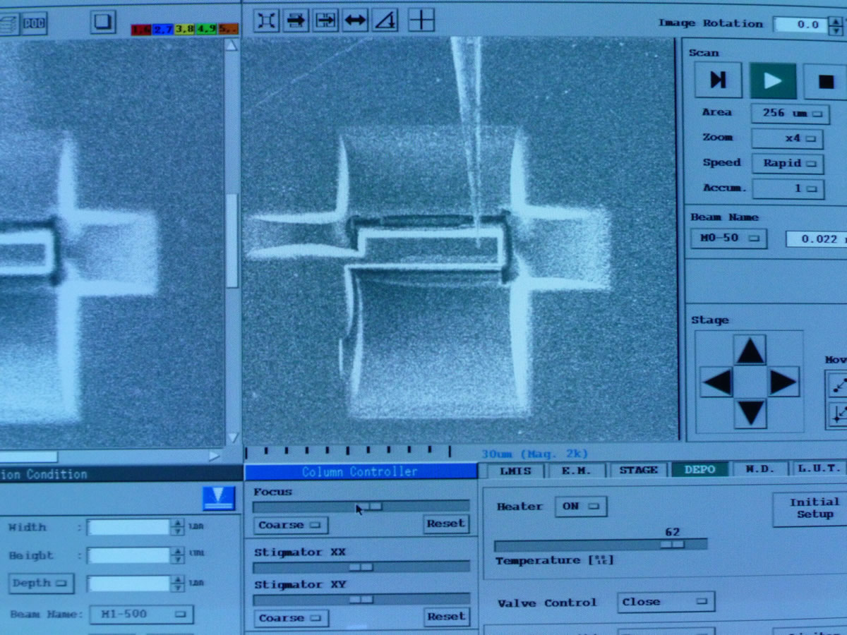
1. Set Area x Zoom = 256 x 1 and position the specimen in the center of the screen.

2. CALL the probe and position the tip of the probe on the far right, but not along the edge of the portion of the specimen to be removed.
NOTE: If you cannot find the probe, change the Area setting to L-SCAN.
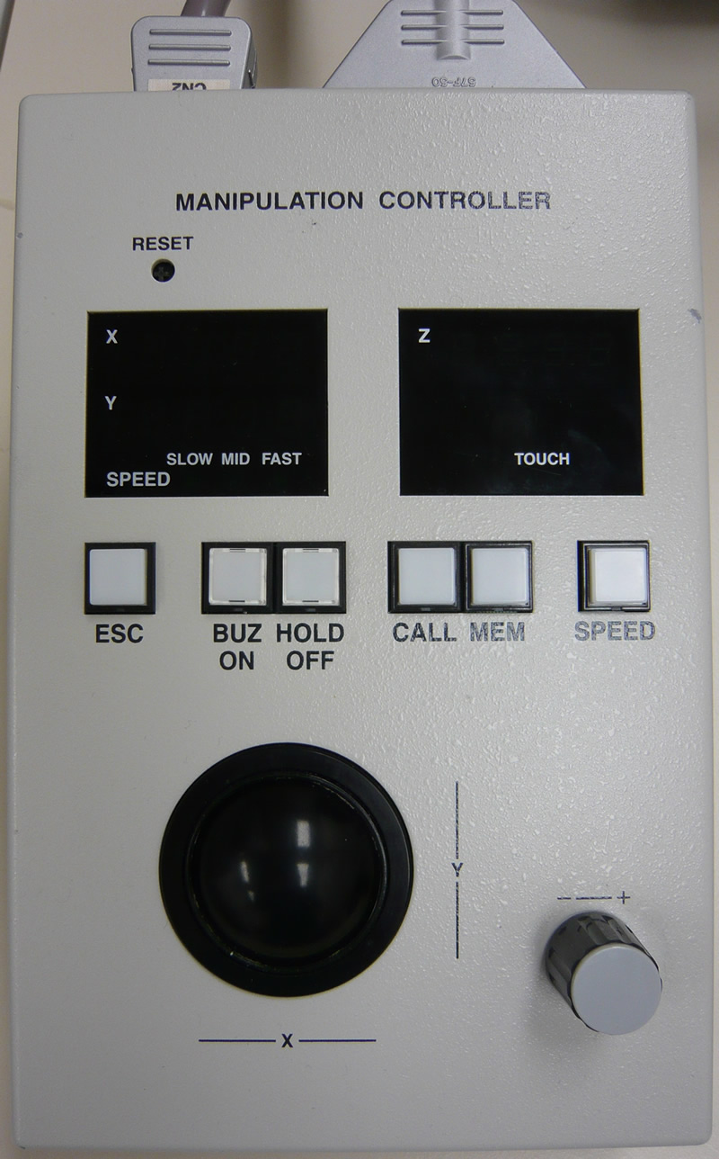
3. Set Area x Zoom = 256 x 4 and press BUZ ON on the MANIPULATION CONTROLLER.
4. Technique for lowering the probe tip:
4.1. While the M0-50 beam is on, you will use the focus knob to alternately focus on the tip and the specimen. The more you have to adjust the focus knob, the greater the distance they are from each other. You will continually have to use the trackball to keep the tip in position.

4.2. Start by using MID speed on the MANIPULATION CONTROLLER. Lower the probe with the Z knob. Focus on the tip, and slide the knob to focus the specimen. Continue this movement until they are near. Change the speed to SLOW until they touch.
4.3. Check the Z position. If your position is less than your first recorded position that was around 765, there will be no collision. Turn off BUZ ON.
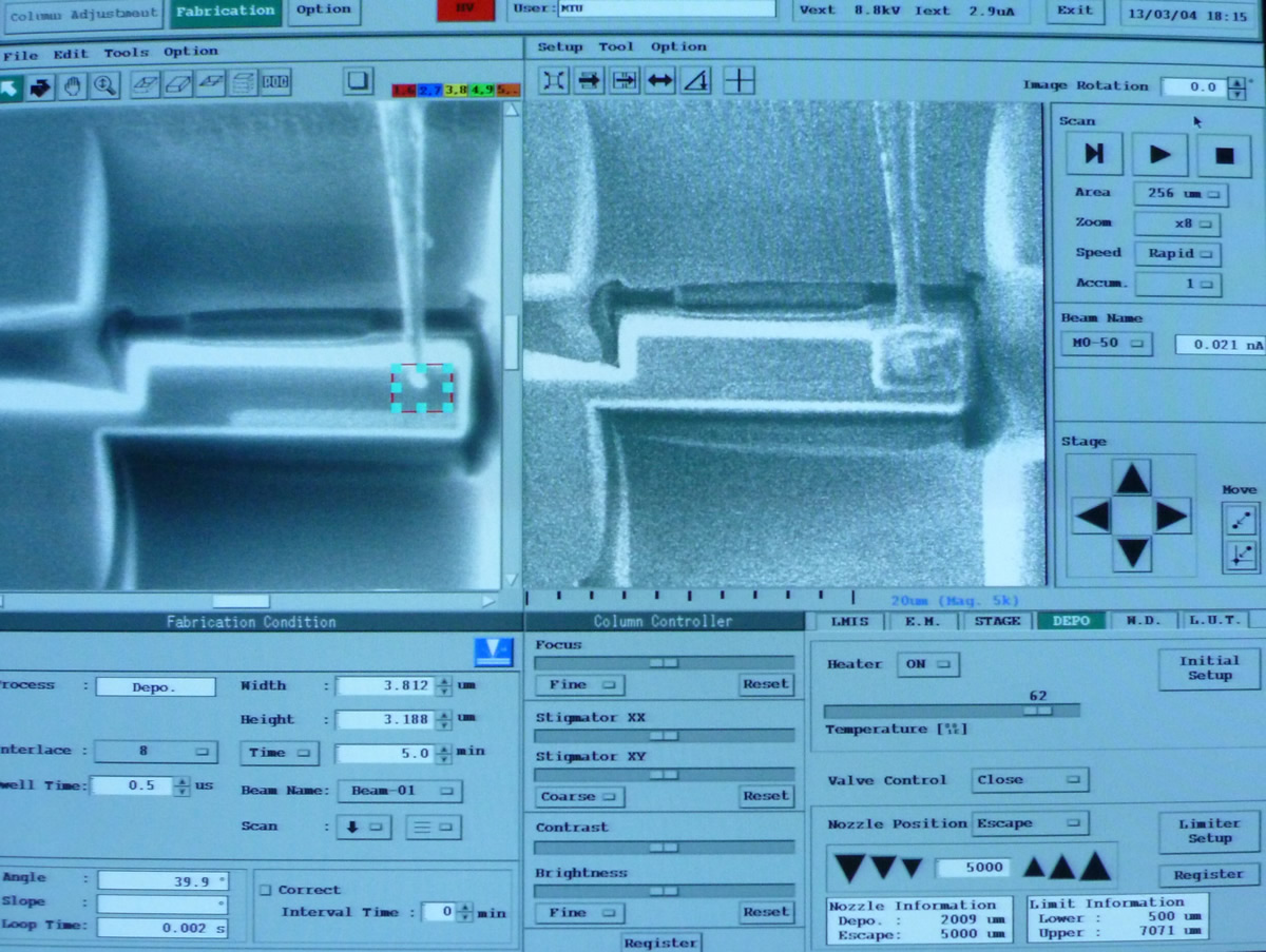
5. At Area x Zoom = 256 x 8, focus and register Beam-01. Click Get Image.
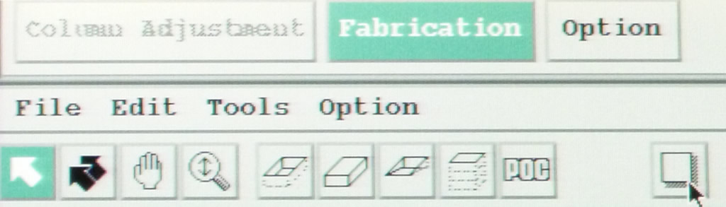
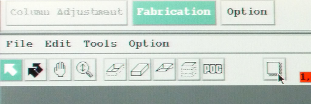
6. Use the DEPO TOOL.
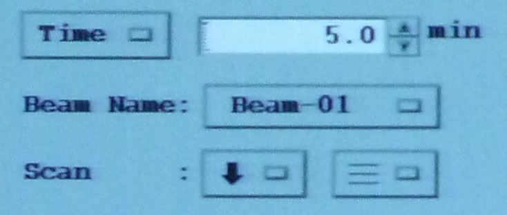
Draw a rectangle with the following parameters:
- Dimensions: ~2.5 x 3
- Time: 5 min.
- Scan: see left image.
7. Place box over the probe tip.
Press Fabrication Start.
8. You may add another protective layer at the same time. The box needs to be at least 2 µm wide.
9. At Area x Zoom = 256 x 8, focus and register M1-100.
10. Press BUZ ON or monitor the TOUCH LED.

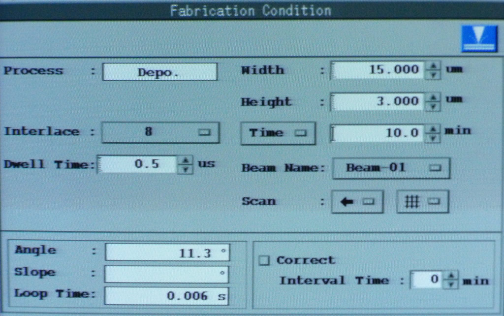
11. To cut the micro-bridge, use the SPUTTER TOOL.
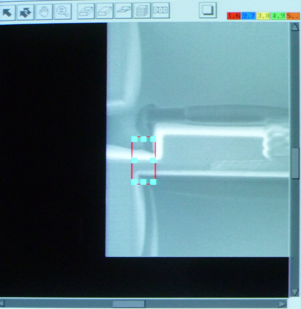
Draw a rectangle.
Use the following parameters:
- Dimensions: ~2.7 x8.6
- Time: 5 min.
- Scan: see image below.
![]()
12. Click the Fabrication Start button. INCREASE CONTRAST to carefully observe. The TOUCH indicator will turn off when bridge is cut. Then press Stop & Close.
NOTE: If the mill is run too long, re-deposition may occur.
NOTE: If the TOUCH LED does not turn off, ask for assistance before proceeding to the next step.
13. Carefully Lift Out, using SLOW speed first. When free, press ESC on the MANIPULATION CONTROLLER.
NOTE: This marks a stopping point for users who will perform the Lift Out over two days.
NOTE: Whether performing the Lift Out over one or two days, proceed to Landing the Probe for Lift Out Technique Part 2 in Operating Procedures under Hitachi FB-2000A FIB.
Operating Procedure: Landing the Probe for Lift Out Technique Part 2