NOTE: If starting from Day 2 of the Lift Out procedure, repeat:
- Alignment for: M0-50, M1-50, Beam-01, M1-100, M1-200, and M1-20 in Operating Procedures under Hitachi FB-2000A FIB, AND
- With the holder in detent, check the Micro-probe position, which is Step 7.1 through 7.10 of the Lift Out Technique in Operating Procedures under Hitachi FB-2000A FIB.
Then continue to Step 14 below.
NOTE: If continuing from Day 1 of the Lift Out procedure, proceed to Step 14 below.
15. If using the Omni Probe grid:
15.1. Load the TEM holder with the Omni Probe grid. (The line around the grid should be facing up.) See Specimen Exchange in Operating Procedures under Hitachi FB-2000A FIB for loading instructions.
15.2. The holder should be in the FIB position. Find the grid by moving the specimen down so you are viewing the top edge of the holder. Start the beam. Proceed to Step 17 below.
16. If NOT using the Omni Probe grid:
16.1. Roll the holder over to the R-T position and find the edge of the grid.
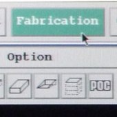
16.2. At Area x Zoom = 256 x 4, focus and register M1-500 for a landing pad. Select File > Quit. Open the Fabrication Menu.
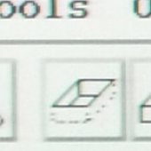
16.3. Use the SPUTTER TOOL to draw a rectangular box with the following parameters:
- Dimensions: ~25 x 5
- Time: 10 min.
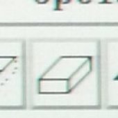
- Scan: see image below.
![]()
NOTE: PAY ATTENTION TO SPECIAL INSTRUCTIONS FOLLOWING THIS STEP.
Place the box so the longer edge just hangs off the top edge of the grid. Click the Fabrication Start button and observe.
16.4. When the milling begins, you will see the white portion gradually lower, creating a gap at the top. When you see the gap, Stop & Close. At this point, reposition the box and re-run so that you are milling the specimen and not the vacuum! Continue with stopping and repositioning until your depth of cut is at least 15 µm and flat. You must repeat until the width equals ~10 µm.
16.5. To check the width:
16.5.1. Change to Area x Zoom = 256 x 1. Roll holder over to the FIB position, keeping your place on the screen with the trackball.
16.5.2. Change to Area x Zoom = 256 x 4. The dimensions should be around 22 µm x 11.5 µm.
19. Move the stage to the upper edge of entire holder by moving the holder down so it is barely on, or even off, the screen. At Area x Zoom = 256 x 1, CALL the probe and raise it to 1500. To position the probe over the landing pad, move the grid up while the probe stays stationary on the center screen. Focus, register, and Get Image.
20. To land the specimen, use the technique described in to Landing the Probe for Lift Out Technique Part 1 in Operating Procedures under Hitachi FB-2000A FIB - Step 4.
21. At Area x Zoom = 256 x 8, focus and register Beam-01.
22. Use the DEPO TOOL to draw a rectangle with the following parameters:
- Dimensions: ~6 x 3 (varies)
- Time: 5 min.
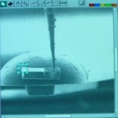
- Scan: see image below.
![]()
23. At Area x Zoom = 256 x 8, focus and register beam M1-200. Press BUZ ON.
24. Use the SPUTTER TOOL to draw a rectangle with the following parameters:
- Dimensions: ~6 x 3
- Time: 5 min.
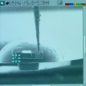
- Scan: see image below.
![]()
Place the box over the top edge of the probe. Observe the mill and press Stop & Close when you hear the "beep."
25. Move the probe up and press ESC on the control board to remove probe.
26. Focus and register M0-50 to observe the results.
